Current sensing in brushless motor drives: shunt vs current sensors
By Warren Pettigrew, Chief Technical Officer
Wednesday, 11 September, 2019

Sensing currents in brushless motor drives is essential, even if it is just for current limiting.
More sophisticated systems such as vector drives have an inner current control loop. It is essential that current readings are consistent if performance and stability is to be optimised over the full operating range.
There are numerous ways to switch a three-phase bridge, which complicates current sensing. It is not always obvious which way current will flow within the bridge especially when considering various braking and drive modes.
The simplest and common format for low-current drives is to place a single shunt in the common negative return line — see Figure 1.

With single-sided switching in analog drives, this format is very unsatisfactory as the average shunt current is not the average motor current. There is a flywheel current circulating within the bridge that does not pass through the shunt resistors. Peak current needs to be sensed but this immediately introduces noise issues.

With digital drives, the shunt current can be sampled during the ON time of the phase in question, but this is still not without its issues. There is near commutation between phases and the time available for sensing current is very short, as it is with a low duty cycle at low speed. To exacerbate the issue further, the shunt current has many high-frequency components which must be sensed through an amplifier that has a very fast slew rate — probably in the order of 20 V/µs. Common mode voltage swings on the shunt must also be considered.

If dynamic braking is introduced, the shunt may not see any of this current so the bridge becomes liable to damage. A lower FET leg would need to be periodically switched on so that the current could be sampled in the shunt.

If good control over braking is required without the need for a specific braking mode, double-sided switching can be instigated. For zero voltage drive, 50% PWM is required. This does mean more time for measuring current at low speed but not at high speed. The shunt sees a current reversal on each PWM cycle.

A possible negative of double-sided switch with low inductance motors is that the ripple current may be high, which increases switching losses in the FETs and I2R losses in the motor and the shunt.
There is a further complication this time regarding sinusoidal commutation. With trapezoidal commutation, only two legs of the bridge are being switched at any one time, but when we move to sinusoidal commutation, all three legs are being switched concurrently. In Figure 6 we can see that the single shunt will see the current of phase C but the shunt will not indicate phase A or phase B current. This simply means that a single shunt is not appropriate for sinusoidal commutation.

To overcome this issue, two shunts can be used, but this still does not address the issue of sensing errors due to low PWM ratios or the issue of dynamic brake currents or circulating currents not being sensed. To this end we will now investigate disparities between actual measured shunt current and armature current in a typical brushless drive.
The system investigated is a modified trapezoidal drive with double-sided switching with three shunts configured as per Figure 7. A Hall effect current sensor is added to measure the actual armature current flowing.

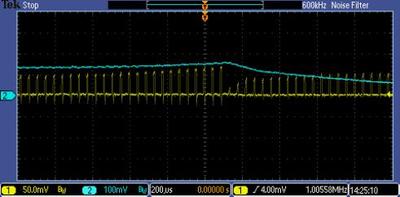
Current readings from the shunt and current sensor can then be compared. Figure 8 depicts the shunt voltage (yellow) and the current sensor output (blue).

Observations
The shunt current is a rectified version of the armature current. For the same current, the depicted magnitude of the sensor output is about 50% greater than the shunt output.
In this drive there are considerable periodic disparities between the shunt current and true armature current.
At times of current maximums, the relationship is more or less consistent but when current is near zero and rising there is poor consistency. There is no consistency when the current is falling.
The reason for the inconsistency has to be that there are circulating currents within the bridge that do not pass through the shunt or overlapping currents as in sinusoidal commutation.
If we magnify the time base, inconsistencies are further depicted as per Figure 9.

Again, during rising current, there is a reasonable relationship between shunt current and armature current, but at the point of commutation shunt current instantly drops to zero and then starts rising again while the armature current gradually falls. Because of inductance, armature current cannot instantly change. It is very likely that it is the inductive current that is not passing through the specific shunt that is causing the discrepancy.
Figure 10 depicts a different period in the cycle.

Armature current is near zero but shunt current is not. At the point of commutation both currents are zero, which is correct, but the shunt current quickly rises and the armature current does not.
We can obviously conclude that the use of shunts in the negative line is a very poor way of measuring currents in many brushless drives. Current flow within three-phase bridges is obviously very complex, especially when one considers the many modes of operation including dynamic braking, regenerative braking, forward and reverse drive and FET leg switching options.
The symptoms of inaccurate current measurement are probably motor vibration and/or load dependent instability. Countering this instability probably means extra damping, which generally results in poorer transient response.
An alternative is to use shunts to measure the phase current, but this immediately introduces the challenge of very big common mode voltage swings on the shunts, which require very precise resistor divider networks and precision amplifiers. Also, when currents get greater than about 30 A, heat in the shunts starts to become an issue.
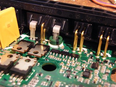
The logical alternative is to employ galvanically isolated current sensors to measure true armature current. These are not necessarily bulky or expensive. An example of a low-cost compact installation of a Raztec sensor is shown in Figure 11.

The toroidal current sensor simply encircles a motor connection. Galvanic isolation completely eliminates common mode effects and true armature current is accurately measured. The output of the sensor is near rail to rail so no amplification is required — current signals can be fed directly to an A/D.
The Raztec RAZC family of sensors is capable of measuring currents of 40–250 A, all with a 10 mm OD. Raztec (New Zealand) has been designing, manufacturing and supplying Hall effect current sensors since 1992.
Please follow us and share on Twitter and Facebook. You can also subscribe for FREE to our weekly newsletter and bimonthly magazine.
Light reshapes semiconductors for advanced optical devices
Researchers have shown how light reshapes Janus semiconductors at the atomic scale, enabling...
Novel method to grow ultrathin semiconductors on electronics
Researchers have developed a technique that could speed up the development of next-generation...
Blue LEDs developed to enhance display performance
Researchers have developed a new method for manufacturing light-emitting diodes (LEDs) that emit...


